We have built and launched hundreds of systems for test, private contract and specisl programs.
A history of innovation in aerospace-
PFS Aerospace knows that physics are quite untapped. What the greatest minds on Earth thought was "impossible" four decades ago, is now achieved. Science is now proving, everyday, that physics is the gift that keeps on giving and that we have employed less than 5% of the potential of propulsive physics. At PFS Aerospace, we have gathered the best and the brightest to scour the possibilities and commercialize the best opportunities.
MARS ROVER
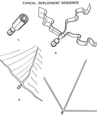
Our staff proposed a landing system to NASA and the key Mars Mission contractors for the Mars mission to NASA from 1968 to 1971. This proposal, engineering drawings and process data was a design for the Mars Rover be shrouded in inflatable bags which would be deployed as the craft was landing on Mars, bouncing the craft safely across the surface in a protective cocoon while would deflate to allow the robotic vehicle to emerge. (Documents and letters from NASA are on file.)
Our staff proposed a landing system to NASA and the key Mars Mission contractors for the Mars mission to NASA from 1968 to 1971. This proposal, engineering drawings and process data was a design for the Mars Rover be shrouded in inflatable bags which would be deployed as the craft was landing on Mars, bouncing the craft safely across the surface in a protective cocoon while would deflate to allow the robotic vehicle to emerge. (Documents and letters from NASA are on file.)
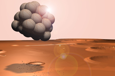
Mars Rover Landing Airbag Landing System Concept (C)1968-2012. Art by PFS Staff.
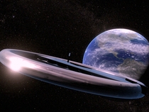
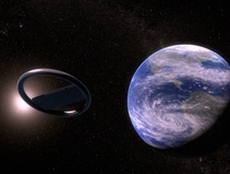
EARTHSTAR
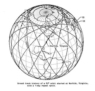
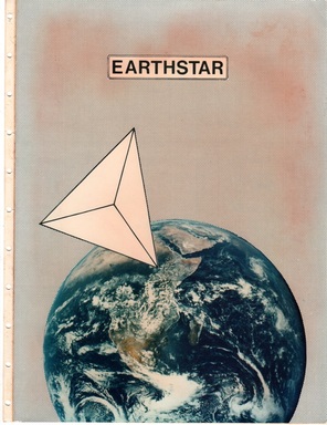
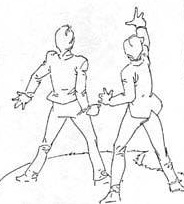
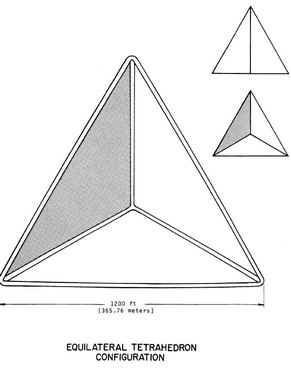
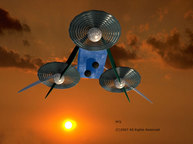
As Director of Promotional Rocketry Marketing for one of America's first private space companies, PFS staff were challenged with a spacecraft that would be temporarily visible to every person on Earth as a tribute to shared national bonds. This was one of the first terrestrial inflatable craft projects ever developed. The massive silver tri-side, rotating, structure inflates in space to a massive dimension and then comets-in for beautiful, and complete, atmospheric burn-up disintegration after use. Staffed by NASA astronauts and executives and re-tasking missile bodies to peaceful purposes, the project was designed to inspire a positive vision to be shared globally. Government cuts caused the project to be put on hold but all of the engineering was completed and calculated, proving the technical potential of the effort. Persons on the ground viewing the EARHSTAR satelliteg, on a typical clear night, would see a four pointed pyramid or tetrahedron shaped structure, very small, rising rapidly above the horizon. It would be very bright against the night sky. It would rotate and sparkle while moving rapidly across the sky. If it traveled directly overhead, it would take 15 minutes to traverse from horizon to horizon. NASA astronaut Deke Slayton was notably involved.
Whole planet viewing potential- 4 billion+
Individual viewings per satellite cycle- 1 billion+
Orbits per cycle- 15
Hours per cycle- 24
Viewing widow per cycle- 15 minutes
Orbital mechanics- Precessional
Orbit altitude- 500 statute miles
Target lifespan of object- 30 days
Nominal view times- 3.5 hours post sunset & 3.5 hours pre sunrise
Velocity vector linear speed- 17,500 mph
Ground viewing circle to Earth-based viewers- 3,800 miles in diameter
Satellite package Earth weight- 1050 lbs.
Primary component material- Tubular construction inflated aluminized Mylar
Secondary component material- Carbon fiber
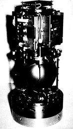
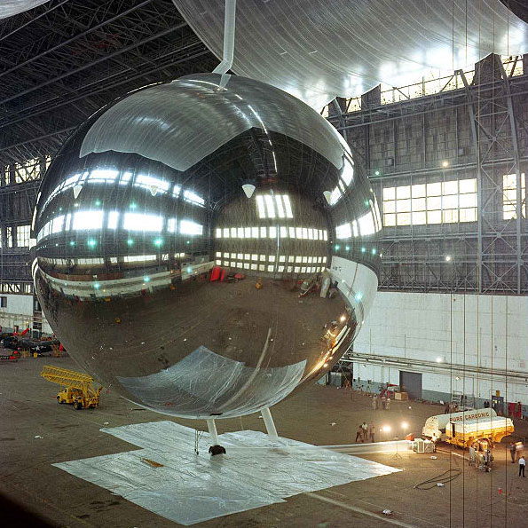
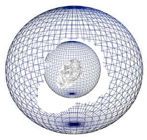
The PAGEOS satellite had provided previous proof-of-concept engineering valdation. (Many people find it hard to believe that such things exist, but just Google "PAGEOS Satellite". The Wikipedia entry on the project is quite nice.) A PAGEOS Test inflation is seen below:
ION DRIVES & MICROTHRUSTERS
Our staff holds the issued US patent on "Microthrusters" and first designed the engineering concept of electronics fab manufactured massed ion propulsion array's. The patent office first rejected the patent as "impossible" but had to back-track when our staff sent the patent office a video of one of the craft flying around in the conference room of the patent attorney's office (The same patent attorney' that Intel uses). Then the patent office rejected the patent because a part of the submitted design had wings on it and they felt that too many aircraft patents had patented wings. We removed the wings as they were not required for the craft to fly. Then the patent office said, "oops", we found a patent that NASA has on this same type of thing. So our staff was put in the position of proving that their engineering and design was BETTER than NASA's! We DID prove that the engineering and design was better than NASA's and the U.S. Government awarded our effort the issued U.S. patent on the technology, overcoming the NASA patent! These patented engineering and design concepts created a way to make the technology functional and this has now been further validated by the MIT microthruster and DARPA proving grounds studies. Our ion space and terrestrial drive technologies provide a many magnitude efficiency increase in ion drive propulsion. Part of the technology is protected by U.S. Patent and the rest is protected by Trade Secret methodologies. Some of our atmospheric systems combine inflatable and microthruster technology for the longest hover times in the industry. Some of our drone systems are weighed in ounces while our competitors must weigh theirs in pounds.
Our staff holds the issued US patent on "Microthrusters" and first designed the engineering concept of electronics fab manufactured massed ion propulsion array's. The patent office first rejected the patent as "impossible" but had to back-track when our staff sent the patent office a video of one of the craft flying around in the conference room of the patent attorney's office (The same patent attorney' that Intel uses). Then the patent office rejected the patent because a part of the submitted design had wings on it and they felt that too many aircraft patents had patented wings. We removed the wings as they were not required for the craft to fly. Then the patent office said, "oops", we found a patent that NASA has on this same type of thing. So our staff was put in the position of proving that their engineering and design was BETTER than NASA's! We DID prove that the engineering and design was better than NASA's and the U.S. Government awarded our effort the issued U.S. patent on the technology, overcoming the NASA patent! These patented engineering and design concepts created a way to make the technology functional and this has now been further validated by the MIT microthruster and DARPA proving grounds studies. Our ion space and terrestrial drive technologies provide a many magnitude efficiency increase in ion drive propulsion. Part of the technology is protected by U.S. Patent and the rest is protected by Trade Secret methodologies. Some of our atmospheric systems combine inflatable and microthruster technology for the longest hover times in the industry. Some of our drone systems are weighed in ounces while our competitors must weigh theirs in pounds.
ENHANCED INFLATABLE LIFTING BODIES
Our staff was the first to engineer and invent inflatable lifting bodies using ion supplementary drives for air-to-space lifting solutions which provide the lowest cost-per-ton launch expense in the market. Physics allows you to escape the Earth's gravity even with a slow lifting body. Rockets are not the only way to get to space.
For historical reference see:
http://en.wikipedia.org/wiki/Orbital_airship
http://en.wikipedia.org/wiki/Escape_velocity
As a researcher once put it:
“to reach “escape velocity or speed”, you need to exert a force to counter gravity equal to 9.8 m/s2 times your mass, but then, you need to do that anyway to keep from falling through your chair. If you had a ladder into space (hey,
don't laugh--it's seriously being considered, if we can make the materials strong enough), you could climb up it at whatever leisurely pace you'd like.
So what is escape speed all bout, then? In order to escape the Earth slowly, you need to continually exert a force to counter gravity. But suppose that instead of a ladder, you have a cannon. You can give your spacecraft-to-be an
initial speed, but after that, it's on its own. If you take a typical cannon, point it straight up, and fire, the cannonball is going to go up for a while, then slow, stop, and fall back to he Earth. Put more powder in your cannon, and
the ball will get higher before this happens.
But suppose you put enough powder in your cannon that the cannonball leaves the muzzle at 11.1 kilometers per second. Now something interesting happens: The cannonball doesn't just get very high before turning around; it never never turns around. Gravity still acts on it, so it'll slow down relative to the earth, but it won't stop. It'll continue forever into the Great Unknown, without your ever having to do more than give it that initial speed. You'll notice I'm saying "escape speed" rather than "escape velocity." The two terms aren't interchangeable. Velocity is a vector, which means it has both magnitude and direction. But escape speed doesn't depend on direction. If I have a high-powered cannon, I can point it wherever I want, up or at any angle, and my cannonball still won't fall back to the Earth. I could even point it down, if there were a tunnel conveniently carved through the Earth so it wouldn't just smack into the surface. Since the direction doesn't matter, just the magnitude, what we have is escape speed.
You may also have noticed that escape speed isn't needed for a rocket. A rocket isn't like a cannon: It's always producing thrust, even after liftoff. So why aren't there any slow rockets? It's largely a matter of cost. Burning rocket
fuel is an expensive way to generate force, so you want to get it over with quickly, in order to waste as little fuel as possible supporting the rocket against gravity. But if you had enough fuel, and weren't in a hurry, you could
ascend as slowly as you liked.”
We get a number of emails from people asking: "So you mean the balloons don't pop"?
People often recall the common experience we all had as a child when our lovely new helium balloon got loose and slowly spiraled up and up. Many of us wondered, as children: "will it go to the moon"?
Back then, no balloon could get to space. Now, inflatable spacecraft have circled the Earth.
With PFS Aerospace: Some of our craft are made of material and configured in a way so they do not pop until they get where we want them to be. Others are timed to pop at certain altitudes. Others are made of material that does not pop at all but our vehicles move higher from that point.
PFS Aerospace invented, engineered and developed the Vectran and Kevlar Pressure Resequencing Lifting Inflatable which DOES NOT POP on it's transport duties to space.
PFS Aerospace also invented, engineered and developed Push Past propulsion technologies which move the lifting inflatable above the terminal buoyancy point where the lifting gas can no longer lift as the space vacuum encroaches.
Why do this? It makes the Cost-To-Space lower, safer and more efficient than that provided by any other company in the business.
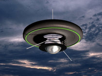
AEROSPHERICAL PROPULSION SYSTEMS
Our staff was the first to engineer and patent file the Aeros-sphere(TM) spherical propulsion technology.
Introduction
Until now, aeronautical flight vehicles have relied, almost exclusively, on a fixed-wing concept to elevate the aircraft and propel it through the atmosphere. One might comment that helicopters are the exception to this rule, but, as is well known, a helicopter utilizes a rotating fixed wing to generate the lift required to propel the aircraft. A cursory examination of NASA’s websites and those of the USAF Research Laboratory reveals that while many concepts for new aircraft are under development, almost all of these rely on the fixed wing concept to generate lift. This information is readily available to the public, so one must assume that there may be other novel concepts under development that are clandestine in nature and, as such, not readily revealed to the public. However, it is safe to assume, given the general nature of aircraft design and development over the past sixty years that even these clandestine designs are also based on the fixed wing concept.
Our team has broken with this tradition and is currently developing a radically new concept for transportation, particularly drone and human-cargo aircraft that relies on the use of a sphere to generate the required lift and propel the spherical aircraft through the atmosphere (or water). This technology has been proven in battle since World War II, (see the movie: "DamBusters") , on every golf course on Earth and in numerous scientific studies; but no one has improved on it as dramatically as our design. The advantages of such a concept over that of the fixed wing concept are manifest. For example, by the very nature of the approach, the entire surface of the sphere is a lifting body, whereas in the fixed wing aircraft, the wings provide the predominant lift. As a result, the spherical aircraft could easily outperform any fixed wing aircraft, in terms of aerodynamics and efficiency. radar signatures can be “tricked” using a sphere design. These features would be directly scalable to any sized sphere. With the rise of interest in autonomous unmanned aircraft, the innate scalability of the spherical aircraft and its attendant capabilities makes this design concept highly desirable. An aircraft carrier could hold and launch many, many more of these types of craft than they now do with a fixed wing craft. A submarine could launch such a runway-free craft. Many other advantages exist.
The approach
This White Paper is intended as an introduction to a radical new flight technology that is under development by our team. The basic concept underlying the technology together with some specific examples of how the technology could be used to fabricate working prototypes is discussed. Further details can be provided under executed NDA.
The theoretical basis for the concept is derived from the fact that a translating sphere is unable to produce aerodynamic lift, because of its geometric symmetry, but a rotating sphere is capable of producing lift as a result of its a viscous interaction with air, water (or supplied molecules in space); the so called Magnus effect. Enhancements, optimizations and support technologies applied to the surface structure and system of the sphere provide the thrust needed to complete the design of the new proposed aeronautical vehicle. In Earth atmosphere and water the system works, as-is. In space, a particle processor is added.
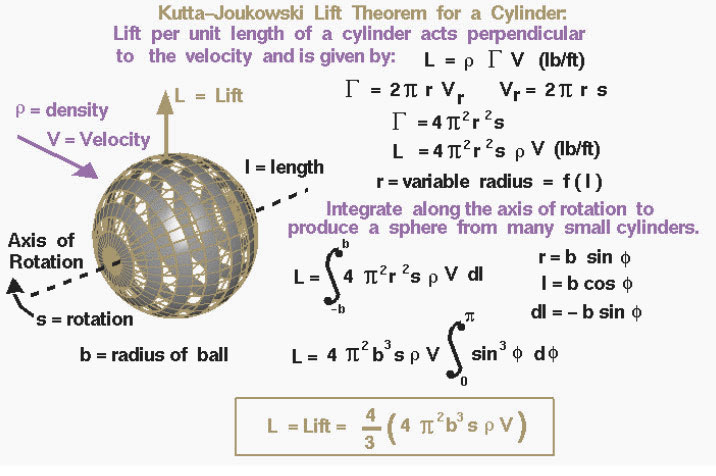
The details of how a spinning ball creates lift are fairly complex. Next to any surface, the molecules of the air stick to the surface. This thin layer of molecules entrains or pulls the surrounding flow of air. For a spinning ball the external flow is pulled in the direction of the spin. If the ball is not translating, there is the spinning, vortex-like flow set up around the spinning ball, neglecting three-dimensional and viscous effects in the outer flow. If the ball is translating through the air at some velocity, then on one side of the ball the entrained flow opposes the free stream flow, while on the other side of the ball, the entrained and free stream flows are in the same direction. Adding the components of velocity for the entrained flow to the free stream flow, on one side of the ball the net velocity is less than free stream; while on the other, the net velocity is greater than free stream. The flow is then turned by the spinning ball, and a force is generated. Because of the change to the velocity field, the pressure field is also altered around the ball. The magnitude of the force can be computed by integrating the surface pressure times the area around the ball. The direction of the force is perpendicular (at a right angle) to the flow direction and perpendicular to the axis of rotation of the ball.
The Kutta-Joukowski lift theorem as referenced in Figure 1 for a single cylinder states the lift per unit length L is equal to the density rho of the air times the strength of the rotation Gamma times the velocity V of the air. The analysis represented in Figure 1 contains many simplified assumptions. The flow field is an ideal fluid field flow which can be generated by superimposing the field flow from an ideal vortex centered on the sphere with a uniform free stream flow. In this ideal model, the fluid (air) has no viscosity so there is no boundary layer despite the fact that viscosity is the real origin of the circulating flow.
The equation above describes the lift force generated on a smooth rotating sphere. In reality, the viscosity of the fluid generates a boundary layer on the sphere and any imperfections on the sphere’s surface will disturb this boundary layer and disrupt the free stream flow. An example of this is the stitches on a baseball. On a baseball, the stitches cause the boundary layer to transition to turbulent flow which affects the amount of aerodynamic drag experienced by the ball. The stitches are not symmetrically distributed around the ball, so the real flow around the ball is separated, unsteady, and not uniform. To account for these real-world effects that have been neglected in our ideal flow model, one must define a lift coefficient. The lift coefficient is an experimentally determined factor that is multiplied times the ideal lift value to produce a real lift value. The ideal simplified model gives the first order effects and explains the relative importance of the factors that affect the lift force on the ball while all of the complex factors are modeled by the lift coefficient. The interaction between the surface of the sphere and the fluid in which it is immersed gives rise to all of the forces experienced by the sphere. The fluid itself is a loose mixture of molecules that are in random motion which generates kinetic energy. This energy is transferred to the sphere as it moves and thereby
interacts with the fluid.
A full description of the details of airflow around a translating sphere can be very complicated and will depend critically on the size and velocity of the air flow. Nevertheless, the net effect on the sphere is rather simple; it results in drag but no lift. In other words, because of the symmetry of the sphere, all the complicated forces and effects of momentum, viscosity, and compressibility simply create a net force tending to drag the sphere in the direction of the free stream velocity, no lift results.
Like any body translating a fluid, in order to create lift it is necessary that there be an imbalance of pressure between the top of the body and the bottom of that body. This can most easily be seen when the body is an airfoil section. On an airfoil the distance an air molecule must follow when flowing over the top of the airfoil is significantly greater than the distance a molecule would flow when passing under the bottom of the airfoil. This difference in path length results in a difference in density and; therefore, a difference in pressure, between the top and bottom. On a sphere, all paths around the surface are great circles and they are the same length. Therefore, the airflow cannot generate a difference in pressure between one side and another. This leads to the simple realization that a purely translating sphere cannot generate lift.
Nevertheless, it is possible for a sphere to generate lift if the sphere is rotating. As discussed above, viscosity is a force that tends to make air molecules stick to the surface with which they are in contact. If a sphere is rotating at the same time it is translating the viscous forces will tend to move air from one side of the sphere to the other thereby creating a density and pressure differential. Any effect that results in creating a pressure differential from one side of the sphere to the other and is perpendicular to the flight velocity will create lift. This effect is referred to as the Magnus effect and is employed whenever topspin or backspin is placed on a tennis ball, for example. Although this effect is real, it is usually small and a relatively inefficient means of generating lift on a sphere.
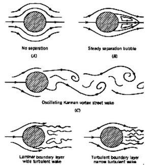
Since drag tends to counteract lift, this explanation leads us to an important conclusion: the drag on a sphere is dominated by the flow separation over its rear face. If this separation could be minimized, the drag experienced by the sphere would be significantly reduced thereby multiplying the Magnus effect. The drag effect is apparent from experimental data, as shown in Figure 2
These data demonstrate that any two spheres that experience the same Reynolds number should exhibit the same aerodynamic characteristics even if the spheres are of different sizes or flying at different speeds. Figure 2 indicates that there is a significant change in the drag on a smooth sphere at a Reynolds number of about 3x10⁵. Below this Re, the drag coefficient is roughly constant at 0.5. above this Re, the drag coefficient again becomes nearly constant at about 0.1. Why should this this particular Reynolds number cause such a large reduction in drag? As it turns out this is the critical point at which the air flowing around the sphere makes an important change. This is where the fluid flow separates appropriately referred to as flow separation. One of the key factors affecting flow separation is the behavior of the boundary layer. The boundary layer is a thin layer of air that lies very close to the surface of a body in motion. It is within this layer that the adverse pressure gradient develops that causes the airflow to separate from the
surface.
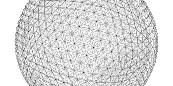
At low Reynolds numbers, the boundary layer remains very smooth and is called laminar. Laminar boundary layers are normally very desirable, because they reduce drag on most shapes. Unfortunately, laminar boundary layers are also very fragile and separate from the surface of a body very easily when they encounter an adverse pressure gradient. At that Reynolds number, however, the boundary layer switches from being laminar to turbulent. The location at which this change in the boundary layer occurs is called the transition point. A turbulent boundary layer causes mixing of the air near the surface that normally results in higher drag. However, the advantage of turbulence is that it speeds up the airflow and gives it more forward momentum. As a result, the boundary layer resists the adverse pressure gradient much longer before it separates from the surface. For example, in the case of a golf ball, increasing the speed is not an option since a golfer can only swing the club so fast, and this velocity is insufficient to exceed the transition Reynolds number. That leaves tripping the boundary layer as the only realistic alternative to reducing the drag on a golf ball. The purpose of the dimples is to do just that-to create a rough surface that promotes an early transition to a turbulent boundary layer. This turbulence helps the flow remain attached to the surface of the ball and reduces the size of the separated wake so as to reduce the drag it generates in flight. When the drag is reduced, the ball flies farther. Some golf ball manufacturers have even started including dimples with sharp corners rather than circular dimples since research indicates that these polygonal shapes reduce drag even more.
Practical Development
Practical implementation of the theories behind the concept of flying spheres will involve the design and
development of devices based on basic concepts described above. Our team has a variety of designs under consideration such as the one described below. In this rendition, the “dimpled” sphere is built of a rigid frame composed of an inorganic composite. This material will afford the frame a very high modulus, but light in weight. The frame will support two turbine engines and will spin on a central axis. Control and fuel lines will feed along the outside of the frame to the engines, emerging from within the sphere at the axis of the frame. An equatorial sequentially triggered MagLev-like track, a bit like a continuous loop rail gun track belt, provides very high speed electric spin, and suspension, of the outer shell. The turbines will provide one of a number of options we developed for forward thrust and steering capability for the sphere. The spin of the sphere will provide lift. Another system, not disclosed in this document, can provide pitch/roll/yaw variation.
The sphere’s pilot, or drone sensor array, will be situated inside of the sphere supported in a second frame within the device. This frame will ride on the inside surface of the sphere in a full set of powered bearings and a gyrocompass will keep the frame stable in early versions and later supported by MagLev mounts in refined embodiments
Our staff was the first to engineer and patent file the Aeros-sphere(TM) spherical propulsion technology.
Introduction
Until now, aeronautical flight vehicles have relied, almost exclusively, on a fixed-wing concept to elevate the aircraft and propel it through the atmosphere. One might comment that helicopters are the exception to this rule, but, as is well known, a helicopter utilizes a rotating fixed wing to generate the lift required to propel the aircraft. A cursory examination of NASA’s websites and those of the USAF Research Laboratory reveals that while many concepts for new aircraft are under development, almost all of these rely on the fixed wing concept to generate lift. This information is readily available to the public, so one must assume that there may be other novel concepts under development that are clandestine in nature and, as such, not readily revealed to the public. However, it is safe to assume, given the general nature of aircraft design and development over the past sixty years that even these clandestine designs are also based on the fixed wing concept.
Our team has broken with this tradition and is currently developing a radically new concept for transportation, particularly drone and human-cargo aircraft that relies on the use of a sphere to generate the required lift and propel the spherical aircraft through the atmosphere (or water). This technology has been proven in battle since World War II, (see the movie: "DamBusters") , on every golf course on Earth and in numerous scientific studies; but no one has improved on it as dramatically as our design. The advantages of such a concept over that of the fixed wing concept are manifest. For example, by the very nature of the approach, the entire surface of the sphere is a lifting body, whereas in the fixed wing aircraft, the wings provide the predominant lift. As a result, the spherical aircraft could easily outperform any fixed wing aircraft, in terms of aerodynamics and efficiency. radar signatures can be “tricked” using a sphere design. These features would be directly scalable to any sized sphere. With the rise of interest in autonomous unmanned aircraft, the innate scalability of the spherical aircraft and its attendant capabilities makes this design concept highly desirable. An aircraft carrier could hold and launch many, many more of these types of craft than they now do with a fixed wing craft. A submarine could launch such a runway-free craft. Many other advantages exist.
The approach
This White Paper is intended as an introduction to a radical new flight technology that is under development by our team. The basic concept underlying the technology together with some specific examples of how the technology could be used to fabricate working prototypes is discussed. Further details can be provided under executed NDA.
The theoretical basis for the concept is derived from the fact that a translating sphere is unable to produce aerodynamic lift, because of its geometric symmetry, but a rotating sphere is capable of producing lift as a result of its a viscous interaction with air, water (or supplied molecules in space); the so called Magnus effect. Enhancements, optimizations and support technologies applied to the surface structure and system of the sphere provide the thrust needed to complete the design of the new proposed aeronautical vehicle. In Earth atmosphere and water the system works, as-is. In space, a particle processor is added.
The details of how a spinning ball creates lift are fairly complex. Next to any surface, the molecules of the air stick to the surface. This thin layer of molecules entrains or pulls the surrounding flow of air. For a spinning ball the external flow is pulled in the direction of the spin. If the ball is not translating, there is the spinning, vortex-like flow set up around the spinning ball, neglecting three-dimensional and viscous effects in the outer flow. If the ball is translating through the air at some velocity, then on one side of the ball the entrained flow opposes the free stream flow, while on the other side of the ball, the entrained and free stream flows are in the same direction. Adding the components of velocity for the entrained flow to the free stream flow, on one side of the ball the net velocity is less than free stream; while on the other, the net velocity is greater than free stream. The flow is then turned by the spinning ball, and a force is generated. Because of the change to the velocity field, the pressure field is also altered around the ball. The magnitude of the force can be computed by integrating the surface pressure times the area around the ball. The direction of the force is perpendicular (at a right angle) to the flow direction and perpendicular to the axis of rotation of the ball.
The Kutta-Joukowski lift theorem as referenced in Figure 1 for a single cylinder states the lift per unit length L is equal to the density rho of the air times the strength of the rotation Gamma times the velocity V of the air. The analysis represented in Figure 1 contains many simplified assumptions. The flow field is an ideal fluid field flow which can be generated by superimposing the field flow from an ideal vortex centered on the sphere with a uniform free stream flow. In this ideal model, the fluid (air) has no viscosity so there is no boundary layer despite the fact that viscosity is the real origin of the circulating flow.
The equation above describes the lift force generated on a smooth rotating sphere. In reality, the viscosity of the fluid generates a boundary layer on the sphere and any imperfections on the sphere’s surface will disturb this boundary layer and disrupt the free stream flow. An example of this is the stitches on a baseball. On a baseball, the stitches cause the boundary layer to transition to turbulent flow which affects the amount of aerodynamic drag experienced by the ball. The stitches are not symmetrically distributed around the ball, so the real flow around the ball is separated, unsteady, and not uniform. To account for these real-world effects that have been neglected in our ideal flow model, one must define a lift coefficient. The lift coefficient is an experimentally determined factor that is multiplied times the ideal lift value to produce a real lift value. The ideal simplified model gives the first order effects and explains the relative importance of the factors that affect the lift force on the ball while all of the complex factors are modeled by the lift coefficient. The interaction between the surface of the sphere and the fluid in which it is immersed gives rise to all of the forces experienced by the sphere. The fluid itself is a loose mixture of molecules that are in random motion which generates kinetic energy. This energy is transferred to the sphere as it moves and thereby
interacts with the fluid.
A full description of the details of airflow around a translating sphere can be very complicated and will depend critically on the size and velocity of the air flow. Nevertheless, the net effect on the sphere is rather simple; it results in drag but no lift. In other words, because of the symmetry of the sphere, all the complicated forces and effects of momentum, viscosity, and compressibility simply create a net force tending to drag the sphere in the direction of the free stream velocity, no lift results.
Like any body translating a fluid, in order to create lift it is necessary that there be an imbalance of pressure between the top of the body and the bottom of that body. This can most easily be seen when the body is an airfoil section. On an airfoil the distance an air molecule must follow when flowing over the top of the airfoil is significantly greater than the distance a molecule would flow when passing under the bottom of the airfoil. This difference in path length results in a difference in density and; therefore, a difference in pressure, between the top and bottom. On a sphere, all paths around the surface are great circles and they are the same length. Therefore, the airflow cannot generate a difference in pressure between one side and another. This leads to the simple realization that a purely translating sphere cannot generate lift.
Nevertheless, it is possible for a sphere to generate lift if the sphere is rotating. As discussed above, viscosity is a force that tends to make air molecules stick to the surface with which they are in contact. If a sphere is rotating at the same time it is translating the viscous forces will tend to move air from one side of the sphere to the other thereby creating a density and pressure differential. Any effect that results in creating a pressure differential from one side of the sphere to the other and is perpendicular to the flight velocity will create lift. This effect is referred to as the Magnus effect and is employed whenever topspin or backspin is placed on a tennis ball, for example. Although this effect is real, it is usually small and a relatively inefficient means of generating lift on a sphere.
Since drag tends to counteract lift, this explanation leads us to an important conclusion: the drag on a sphere is dominated by the flow separation over its rear face. If this separation could be minimized, the drag experienced by the sphere would be significantly reduced thereby multiplying the Magnus effect. The drag effect is apparent from experimental data, as shown in Figure 2
These data demonstrate that any two spheres that experience the same Reynolds number should exhibit the same aerodynamic characteristics even if the spheres are of different sizes or flying at different speeds. Figure 2 indicates that there is a significant change in the drag on a smooth sphere at a Reynolds number of about 3x10⁵. Below this Re, the drag coefficient is roughly constant at 0.5. above this Re, the drag coefficient again becomes nearly constant at about 0.1. Why should this this particular Reynolds number cause such a large reduction in drag? As it turns out this is the critical point at which the air flowing around the sphere makes an important change. This is where the fluid flow separates appropriately referred to as flow separation. One of the key factors affecting flow separation is the behavior of the boundary layer. The boundary layer is a thin layer of air that lies very close to the surface of a body in motion. It is within this layer that the adverse pressure gradient develops that causes the airflow to separate from the
surface.
At low Reynolds numbers, the boundary layer remains very smooth and is called laminar. Laminar boundary layers are normally very desirable, because they reduce drag on most shapes. Unfortunately, laminar boundary layers are also very fragile and separate from the surface of a body very easily when they encounter an adverse pressure gradient. At that Reynolds number, however, the boundary layer switches from being laminar to turbulent. The location at which this change in the boundary layer occurs is called the transition point. A turbulent boundary layer causes mixing of the air near the surface that normally results in higher drag. However, the advantage of turbulence is that it speeds up the airflow and gives it more forward momentum. As a result, the boundary layer resists the adverse pressure gradient much longer before it separates from the surface. For example, in the case of a golf ball, increasing the speed is not an option since a golfer can only swing the club so fast, and this velocity is insufficient to exceed the transition Reynolds number. That leaves tripping the boundary layer as the only realistic alternative to reducing the drag on a golf ball. The purpose of the dimples is to do just that-to create a rough surface that promotes an early transition to a turbulent boundary layer. This turbulence helps the flow remain attached to the surface of the ball and reduces the size of the separated wake so as to reduce the drag it generates in flight. When the drag is reduced, the ball flies farther. Some golf ball manufacturers have even started including dimples with sharp corners rather than circular dimples since research indicates that these polygonal shapes reduce drag even more.
Practical Development
Practical implementation of the theories behind the concept of flying spheres will involve the design and
development of devices based on basic concepts described above. Our team has a variety of designs under consideration such as the one described below. In this rendition, the “dimpled” sphere is built of a rigid frame composed of an inorganic composite. This material will afford the frame a very high modulus, but light in weight. The frame will support two turbine engines and will spin on a central axis. Control and fuel lines will feed along the outside of the frame to the engines, emerging from within the sphere at the axis of the frame. An equatorial sequentially triggered MagLev-like track, a bit like a continuous loop rail gun track belt, provides very high speed electric spin, and suspension, of the outer shell. The turbines will provide one of a number of options we developed for forward thrust and steering capability for the sphere. The spin of the sphere will provide lift. Another system, not disclosed in this document, can provide pitch/roll/yaw variation.
The sphere’s pilot, or drone sensor array, will be situated inside of the sphere supported in a second frame within the device. This frame will ride on the inside surface of the sphere in a full set of powered bearings and a gyrocompass will keep the frame stable in early versions and later supported by MagLev mounts in refined embodiments
ITEX
The ITEX Project is the most ambitious system PFS, or any of our aerospace partners, have ever attempted. This person-capable craft deploys a hybrid combination of previous technologies along with an entirely new technology solution. Constructed concurrently in the U.S. and Australia, this system seeks to break cost and performance barriers for
space/terrestrial mobility.
(Patents issued and pending. Intellectual property aggressively enforced.)